ICGOO在线商城 > 继电器 > 信号继电器,高达 2 A > G6K-2F-Y DC3
 Datasheet下载
- 型号: G6K-2F-Y DC3
- 制造商: Omron Electronics LLC
- 库位|库存: xxxx|xxxx
- 要求:
| 数量阶梯 | 香港交货 | 国内含税 |
| +xxxx | $xxxx | ¥xxxx |
查看当月历史价格
查看今年历史价格
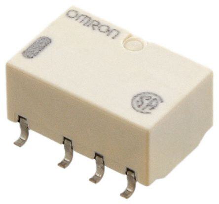
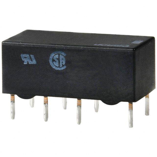
G6K-2F-Y DC3产品简介:
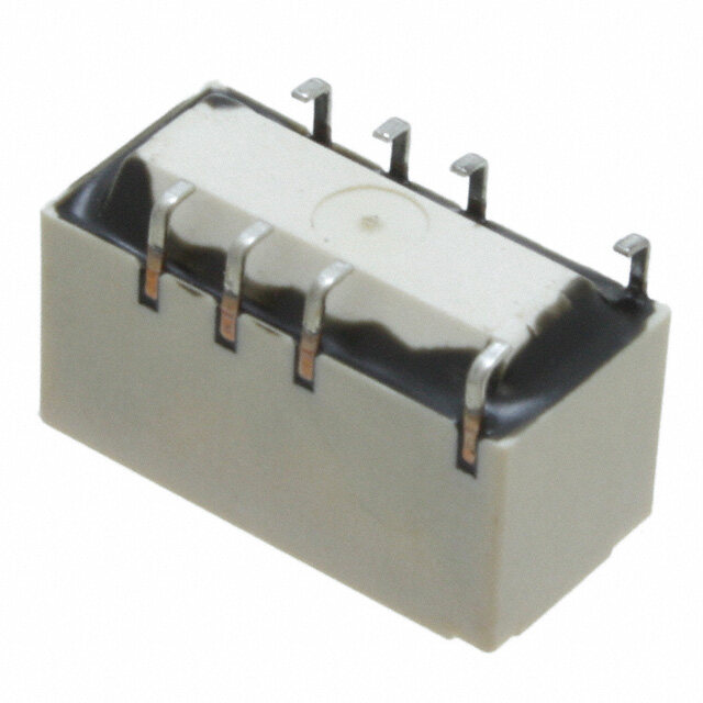
ICGOO电子元器件商城为您提供G6K-2F-Y DC3由Omron Electronics LLC设计生产,在icgoo商城现货销售,并且可以通过原厂、代理商等渠道进行代购。 G6K-2F-Y DC3价格参考¥21.02-¥36.06。Omron Electronics LLCG6K-2F-Y DC3封装/规格:信号继电器,高达 2 A, Telecom Relay DPDT (2 Form C) Surface Mount。您可以下载G6K-2F-Y DC3参考资料、Datasheet数据手册功能说明书,资料中有G6K-2F-Y DC3 详细功能的应用电路图电压和使用方法及教程。
Omron Electronics Inc-EMC Div 的 G6K-2F-Y DC3 是一款信号继电器,额定电流高达 2 A,适用于需要高可靠性和紧凑设计的电子控制系统。该继电器采用直流3V线圈电压驱动,具有超小型密封结构,适合在空间受限的设备中使用。

典型应用场景包括:通信设备(如路由器、交换机)中的信号切换与隔离;办公自动化设备(如打印机、复印机)中的电路控制;工业自动化控制系统中的逻辑信号传递;医疗电子设备中对安全性和稳定性要求较高的信号通断操作;以及测试测量仪器中的精密电路切换。

G6K-2F-Y DC3 具备优良的抗干扰能力和长寿命特性,能够在较宽温度范围内稳定工作,适合在电磁环境复杂或对可靠性要求高的场合使用。其密封结构有效防止灰尘和湿气侵入,提升了在恶劣环境下的运行稳定性。

此外,该继电器符合环保标准,无铅设计,适用于现代绿色电子产品制造。由于其快速响应、低功耗和高绝缘性能,也常用于电池供电设备和便携式仪器中,实现高效节能的信号控制。总之,G6K-2F-Y DC3 是高性能信号控制的理想选择,广泛应用于电子、工业、通信和医疗等多个领域。
| 参数 | 数值 |
| 产品目录 | |
| 描述 | RELAY TELECOM DPDT 1A 3V |
| 产品分类 | |
| 品牌 | Omron Electronics Inc-EMC Div |
| 数据手册 | |
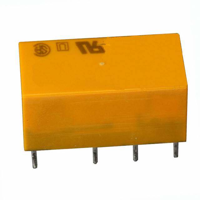
| 产品图片 |
|
| 产品型号 | G6K-2F-Y DC3 |
| rohs | 无铅 / 符合限制有害物质指令(RoHS)规范要求 |
| 产品系列 | G6K |
| 产品培训模块 | http://www.digikey.cn/PTM/IndividualPTM.page?site=cn&lang=zhs&ptm=25458 |
| 产品目录绘图 |
|
| 产品目录页面 | |
| 关闭电压(最小值) | 0.3 VDC |
| 其它名称 | G5LN8010G |
| 其它有关文件 | |
| 包装 | 管件 |
| 安装类型 | 表面贴装 |
| 导通电压(最大值) | 2.4 VDC |
| 工作时间 | 3ms |
| 工作温度 | -40°C ~ 70°C |
| 开关电压 | 125VAC,60VDC - 最小值 |
| 标准包装 | 500 |
| 特性 | - |
| 端子类型 | 鸥翼型 |
| 线圈功率 | 100 mW |
| 线圈电压 | 3VDC |
| 线圈电流 | 33mA |
| 线圈电阻 | 91 欧姆 |
| 线圈类型 | 无锁存 |
| 继电器类型 | 电信 |
| 触头外形 | DPDT(2 C 型) |
| 触头材料 | Silver(Ag),Gold(Au) |
| 释放时间 | 3ms |
| 额定接触(电流) | 1A |

-2F(-Y)%20Series.jpg)


- 商务部:美国ITC正式对集成电路等产品启动337调查
- 曝三星4nm工艺存在良率问题 高通将骁龙8 Gen1或转产台积电
- 太阳诱电将投资9.5亿元在常州建新厂生产MLCC 预计2023年完工
- 英特尔发布欧洲新工厂建设计划 深化IDM 2.0 战略
- 台积电先进制程称霸业界 有大客户加持明年业绩稳了
- 达到5530亿美元!SIA预计今年全球半导体销售额将创下新高
- 英特尔拟将自动驾驶子公司Mobileye上市 估值或超500亿美元
- 三星加码芯片和SET,合并消费电子和移动部门,撤换高东真等 CEO
- 三星电子宣布重大人事变动 还合并消费电子和移动部门
- 海关总署:前11个月进口集成电路产品价值2.52万亿元 增长14.8%
PDF Datasheet 数据手册内容提取
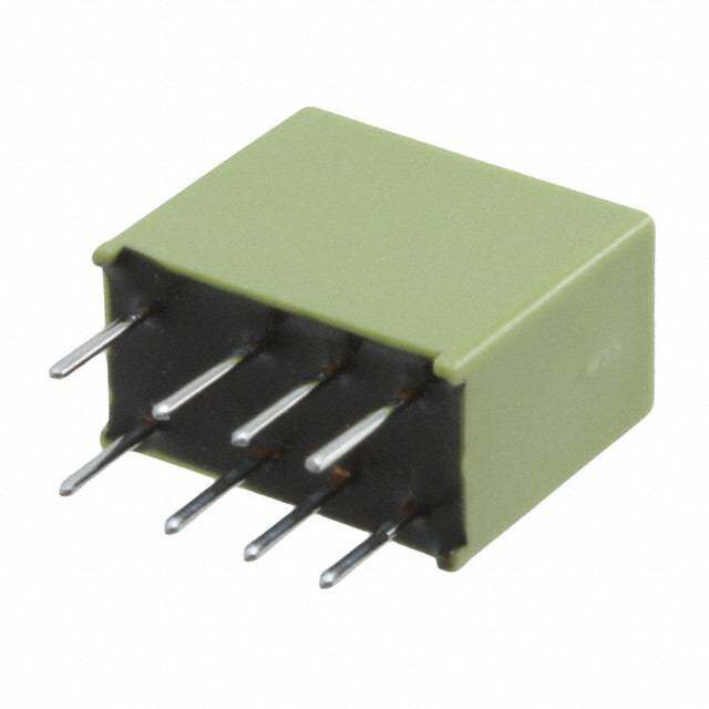
G6K Surface Mounting Relay Surface Mounting Relay with the World’s Smallest Mounting Area •Subminiature model as small as 5.2 (H) × 6.5 (W) × 10 (L) mm is ideal for high-density mounting (G6K(U)-2F(-Y)). •Low profile of 5.2 mm improves mounting efficiency (G6K(U)-2F(-Y)). •Light weight of 0.7 g contributes to higher speed mounting. •Surface mounting terminal models incorporate a unique terminal structure with high infrared irradiation efficiency which allows the terminal temperature to rise easily when mounting the IRS, thus ensuring excellent soldering. •Ensures a dielectric strength of 1,500 VAC and conforms to FCC Part 68 (i.e., withstanding an impulse withstand voltage of 1,500V for 10 × 160 μs). •-Y models offer an impulse withstand voltage of 2,500 V for 2 × 10 μs (conforms to Telcordia specifications) by optimizing the distance between coil and contacts. •Standard model conforms to UL/CSA standards, certified by BSI (EN62368-1). •Models available with a 2.54-mm terminal pitch. •Rated carry current: 2A. RoHS Compliant ■Model Number Legend G 6 K G6K@-@@-@ 1 2 3 4 1. Relay function None: Single-side stable model U : Single-winding latching model 2. Number of contact poles/Contact form 2 : 2-pole/DPDT (2c) 3. Terminal Shape F : Outside-L surface mounting terminals G: Inside-L surface mounting terminals P: PCB terminals 4. Terminal Arrangement - Impulse withstand voltage None:Terminal Arrangement 2.54 mm pitch Impulse withstand voltage Between coil and contacts (1.5 kV for 10 × 160 μs) Y :Terminal Arrangement Between Coil-Contact Terminal 3.2 mm Between Contact Terminal 2.2 mm pitch Impulse withstand voltage Between coil and contacts (Conforms to Telcordia specifications: 2.5 kV for 2 × 10 μs, 1.5kV for 10 × 160 μs) ■Application Examples •Telecommunication equipment •Office automation machines •Test and measurement equipment •Building automation equipment •Security equipment •Industrial equipment •Amusement equipment •Home appliances 1
G6K Surface Mounting Relay ■Ordering Information ●Surface Mounting Terminal Standard Models Packing Tube Packing Tape Packing Enclosure Relay Rated coil Minimum Rated coil Minimum Minimum ordering unit Contact form Model Model rating Function voltage packing unit voltage packing unit (tape packing) 3 VDC 3 VDC 4.5 VDC 4.5 VDC G6K-2F 5 VDC G6K-2F-TR 5 VDC 12 VDC 12 VDC 24 VDC 24 VDC 3 VDC 3 VDC Highly insulated 4.5 VDC Highly insulated 4.5 VDC G6K-2F-Y 5 VDC G6K-2F-Y-TR 5 VDC 12 VDC 12 VDC Single-side 24 VDC 24 VDC stable 3 VDC 3 VDC 4.5 VDC 4.5 VDC G6K-2G 5 VDC G6K-2G-TR 5 VDC 12 VDC 12 VDC 24 VDC 24 VDC Fully sealed DPDT (2c) 50 pcs/tube 900 pcs/reel 1,800 pcs/2 reels 3 VDC 3 VDC Highly insulated 4.5 VDC Highly insulated 4.5 VDC G6K-2G-Y 5 VDC G6K-2G-Y-TR 5 VDC 12 VDC 12 VDC 24 VDC 24 VDC G 3 VDC 3 VDC 6 Highly insulated 4.5 VDC Highly insulated 4.5 VDC K G6KU-2F-Y 5 VDC G6KU-2F-Y-TR 5 VDC 12 VDC 12 VDC Single- 24 VDC 24 VDC winding 3 VDC 3 VDC latching Highly insulated 4.5 VDC Highly insulated 4.5 VDC G6KU-2G-Y 5 VDC G6KU-2G-Y-TR 5 VDC 12 VDC 12 VDC 24 VDC 24 VDC ●PCB Terminal Standard Models Rated coil Minimum Enclosure rating Relay Function Contact form Model voltage packing unit 3 VDC 4.5 VDC G6K-2P 5 VDC 12 VDC 24 VDC Single-side stable 3 VDC 4.5 VDC Highly insulated Fully sealed DPDT (2c) 5 VDC 50 pcs/tube G6K-2P-Y 12 VDC 24 VDC 3 VDC 4.5 VDC Single-winding Highly insulated 5 VDC latching G6KU-2P-Y 12 VDC 24 VDC Note 1.When ordering, add the rated coil voltage to the model number. Example: G6K-2F DC3 Rated coil voltage However, the notation of the coil voltage on the product case as well as on the packing will be marked as @@ VDC. Note 2.When ordering tape packing, add -TR" to the model number. Be sure since -TR" is not part of the relay model number, it is not marked on the relay case. When ordering tape packing, minimum order unit is 2 reels (900 pcs ✕ 2 = 1,800 pcs). Note 3.Surface mounting terminal (SMT) standard models are shipped in moisture-proof package. PCB terminal standard types do not require moisture proof packaging and therefore shipped in non-moisture-proof package. 2
G6K Surface Mounting Relay ■Ratings Coil: Single-side Stable Models Contacts Item Rated Coil Must operate Must release Max. voltage Power Item Load Resistive load current resistance voltage (V) voltage (V) (V) consumption Contact type Bifurcated crossbar Rated voltage (mA) (Ω) % of rated voltage (mW) Contact material Ag (Au-Alloy contact) 3 VDC 33.0 91 0.3 A at 125 VAC, Rated load 4.5 VDC 23.2 194 1 A at 30 VDC Approx. 5 VDC 21.1 237 80% max. 10% min. 150% Rated carry current 2 A 100 12 VDC 9.1 1,315 Max. switching voltage 125 VAC, 60 VDC 24 VDC 4.6 5,220 Max. switching current 1 A Note 1.The rated current and coil resistance are measured at a coil temperature of 23°C with a tolerance of ±10%. Note 2.The operating characteristics are measured at a coil temperature of 23°C. Note 3.The maximum voltage is the highest voltage that can be imposed on the relay coil instantaneously. Coil: Single-winding Latching Models (G6KU-2F-Y, G6KU-2G-Y, G6KU-2P-Y) Item Rated Coil Must operate Must release Max. voltage Power current resistance voltage (V) voltage (V) (V) consumption Rated voltage (mA) (Ω) % of rated voltage (mW) 3 VDC 33.0 91 4.5 VDC 23.2 194 Approx. 5 VDC 21.1 237 75% max. 75% max. 150% 100 12 VDC 9.1 1,315 24 VDC 4.6 5,220 G Note 1.The rated current and coil resistance are measured at a coil temperature of 23°C with a tolerance 6 of ±10%. K Note 2.The operating characteristics are measured at a coil temperature of 23°C. Note 3.The maximum voltage is the highest voltage that can be imposed on the relay coil instantaneously. ■Characteristics Relay Function Single-side stable models Single-winding latching models Item G6K-2F, G6K-2G, G6K-2PG6K-2F-Y, G6K-2G-Y, G6K-2P-YG6KU-2F-Y, G6KU-2G-Y, G6KU-2P-Y Contact resistance *1 100 mΩ max. Operating (set) time 3 ms max. Release (reset) time 3 ms max. Minimum set/reset signal width − 10 ms Insulation resistance *2 1,000 MΩ min. (at 500 VDC) Between coil and 1,500 VAC, 50/60 Hz for 1 min contacts Dielectric Between contacts of 1,000 VAC, 50/60 Hz for 1 min strength different polarity Between contacts of 750 VAC, 50/60 Hz for 1 min the same polarity Between coil and 1,500 V (10 × 160 μs) 2,500 V (2 × 10 μs), 1,500 V (10 × 160 μs) contacts Impulse Between contacts of withstand different polarity voltage 1,500 V (10 × 160 μs) Between contacts of the same polarity Vibration Destruction 10-55-10 Hz, 2.5 mm single amplitude (5 mm double amplitude) and 55 to 500 Hz, 300 m/s2 resistance Malfunction 10-55-10 Hz, 1.65 mm single amplitude (3.3 mm double amplitude) and 55 to 500 Hz, 200 m/s2 Shock Destruction 1,000 m/s2 resistance Malfunction 750 m/s2 Mechanical 50,000,000 operations min. (at 36,000 operations/hour) Durability Electrical 100,000 operations min. (with a rated load at 1,800 operations/hour) Failure rate (P level) *3 10 μA at 10 mVDC Ambient operating temperature -40 to 70°C (with no icing or condensation) Ambient operating humidity 5% to 85% Weight Approx. 0.7 g Note:The above values are initial values. *1. The contact resistance was measured with 10 mA at 1 *3. This value was measured at a switching frequency of 120 VDC with a voltage-drop method. operations/min and the criterion of contact resistance is *2. The insulation resistance was measured with a 500 VDC 50Ω. This value may vary depending on the switching megohmmeter applied to the same parts as those used for frequency and operating environment. Always checking the dielectric strength. double-check relay suitability under actual operating conditions. 3
G6K Surface Mounting Relay ■Engineering Data ●Maximum Switching Capacity ●Durability ●Ambient Temperature vs. Maximum Coil Voltage Switching current (A) 107531 4Durability (x10 operations)1531,0000530000000 3AS10,mw8 iV0btc0iDeh Coninpt gretee rfsmarietspiqotieuvnreesan /tlhuocoryaeu:d:r 23°C Maximum coil voltage (%)221221505505000000 0.7 AC resistive load 110000 0.5 10 DC resistive load 125 VAC resistive load 0.3 5 Ambient temperature: 23°C Switching frequency: 5500 3 1,800 operations/hour 0.1 1 00 10 30 50 70 100 300 500 700 1,000 0 0.2 0.4 0.6 0.8 1 1.2 −40 −20 0 20 40 60 80 100 Switching voltage (V) Switching current (A) Ambient temperature (°C) Note: The maximum coil voltage refers to the maximum value in a varying range of operating power voltage, not a continuous voltage. ●Ambient Temperature vs. Carry ●Ambient Temperature vs. Must ●Ambient Temperature vs. Must Current Operate or Must Release Voltage Set or Must Reset Voltage G6K-2G (F/P), G6K-2G (F/P)-Y G6KU-2G (F/P)-Y GK6 Carry current (A)2211....4062 On the basis of rated voltage (%)109876540000000 mm−Xainx.. On the basis of rated voltage (%)10987600000 Max. estimated vma−Xlauxe. 0.8 min. 30 m−ax. 50 X 0.4 20 min. 40 10 Must operate voltage Must release voltage -040 -20 0 20 40 60 80 100 −060 −40 −20 0 20 40 60 80 100 3−060 −40 −20 0 20 40 60 80 100 Ambient temperature (°C) Ambient temperature (°C) Ambient temperature (°C) ●Shock Malfunction ●Electrical Durability (with Must Operate ●Electrical Durability and Must Release Voltage) *1 (Contact Resistance) *1 G6K-2G (F/P), G6K-2G (F/P)-Y G6K-2G (F/P), G6K-2G (F/P)-Y 1,0X00 200Y18642,0000000000De0nee-rgEizneedrgized1,0Z00 On the basis of rated voltage (%)108640000 TwSSNMewiautshumimtt sc apcbthn oleoien nrop: g dopeG iffert r6iaRoreKatnqeet-sui l2oav:eG noy1n sl trcA:aa y1g t:re 0ee1 os,p8ifcs 05sti00v %eo ploearadt iaotn 3s0/h VDC mmainx.. ΩContact resistance (m)1,053100000000 TaoSoSNtfpewa uC35esmimott00rc anpc %bhVttoleiieaonDnr:cn g dCotGs iffrt / r6iwehRoeKsinqeti-hssul2a t:eaGa y1nnns c cA:o ye1 p:r 0ee1 sr,p8aics0tstioi0vn e rlaotaed NNOC ccoonmmnttaaaacxxct..t 1,000 400 1,000 50 min. Z' 600 X' min. ShoXck direcXtio'ns 800 20 Must release voltage mmainx.. 30 Y Z 1,000Y' USanmit: pmle/:s 2G6K-2G Z' Number of Relays: 10 pcs 0 10 CondYi'tions:Shock is applied in ±X, ±Y, and ±Z 0.001 0.01 O0p.1e rating fr1e quency1 (0x 103 op1e0r0ations) 0.001 0.01 O0p.1e rating fr1e quency1 (0x 103 op1e0r0ations) directions three times each with and without energizing the Relays to check the number of contact malfunctions. ●Contact Reliability Test *1, *2 ●Mutual Magnetic Interference ●Mutual Magnetic Interference G6K-2G (F/P), G6K-2G (F/P)-Y G6K-2G (F/P), G6K-2G (F/P)-Y G6K-2G (F/P), G6K-2G (F/P)-Y ΩContact resistance (m)1,053000000SNTloSooppeawuaeesmmdittrrc aapbachttleoteiii oonrn1: nn god0G s fi rft m/6ariRhoeKt eenqV- ls2uaDo:Gey fC1 ns50 c:0w y1μ%i:0t Ah7 p ,ra2cen0ss 0is tive NNOC ccoommnntaitnaax.cc.tt De-eSnearmgipzleed Change rate on thebasis of initial value (%) +++−−−3211230000000Initial sAtavegreage vTaeluset SamplDee-energizedChange rate on thebasis of initial value (%) +++−−−3211230000000Initial sAtavegreage vTaeluset 100 531000 mmmmaaiinnxx.... ESnearmgipzleed Change rate on thebasis of initial value (%) +++−−−3211230000000Initial sAtavegreage vTaeluset Sample EnergizedChange rate on thebasis of initial value (%) +++−−−3211230000000Initial sAtavegreage vTaeluset 0.001 0.01 0.1 1 10 100 1,000 10,000 100,000 Must operate voltage Must operate voltage Operating frequency (x103 operations) Must release voltage Must release voltage *1. The test was conducted at an ambient temperature of 23°C. *2. The contact resistance data are periodically measured reference values and are not values from each monitoring operation. Contact resistance values will vary according to the switching frequency and operating environment, so be sure to check operation under the actual operating conditions before use. 4
G6K Surface Mounting Relay ●External Magnetic Interference G6K-2G (F/P), G6K-2G (F/P)-Y (Average value) (Average value) (Average value) %) +30 %) +30 %) +30 e ( S N S N e ( S N S N e ( S N S N u u u al val +20 al val +20 al val +20 niti niti niti asis of i +10 asis of i +10 asis of i +10 b b b e e e n th 0 n th 0 n th 0 o o o e e e at at at e r −10 e r −10 e r −10 g g g n n n a a a h h h C C C −20 −20 −20 Sample: G6K-2G Must operate voltage Sample: G6K-2G Must operate voltage Sample: G6K-2G Must operate voltage −30 Number of Relays: 10 pcs Must release voltage −30 Number of Relays: 10 pcs Must release voltage −30 Number of Relays: 10 pcs Must release voltage −1,200 −800 −400 0 400 800 1,200 −1,200 −800 −400 0 400 800 1,200 −1,200 −800 −400 0 400 800 1,200 External magnetic field (A/m) External magnetic field (A/m) External magnetic field (A/m) ●High-frequency Characteristics ●High-frequency Characteristics ●High-frequency Characteristics (Isolation) *1, *2 (Insertion Loss) ) *1, *2 (Return Loss) *1, *2 G6K-2G (F/P), G6K-2G (F/P)-Y G6K-2G (F/P), G6K-2G (F/P)-Y G6K-2G (F/P),G6K-2G (F/P)-Y (Average value (initial)) (Average value (initial)) (Average value (initial)) Isolation (dB) 1230000 SNaummpbleer: oGf 6RKe-l2aGys: 10 pcs nsertion loss (dB)0.01 Return loss (dB) 12000 SNaummpbleer: oGf 6RKe-l2aFy-sY: 5 pcs 111...4335V.SWR GK6 I 40 0.2 30 1.25 Return loss 50 40 1.2 60 0.3 50 1.15 70 60 1.1 80 0.4 90 Sample: G6K-2G 70 V.SWR 1.05 Number of Relays: 10 pcs 100 0.5 80 1 1 10 100 1 10 100 1 10 100 Frequency (MHz) Frequency (MHz) Frequency (MHz) ●Must Operate and Must Release ●Must Operate and Must Release ●Vibration Resistance Time Distribution *1 Bounce Time Distribution *1 G6K-2G (F/P), G6K-2G (F/P)-Y G6K-2G (F/P), G6K-2G (F/P)-Y G6K-2G (F/P) , G6K-2G (F/P)-Y Number of contacts 6400 SN50au mmpcpbsleer: oGf 6RKe-l2aGys: MvMvoouullttssaattgg oreeepleearastee Number of contacts 6400 MMuusstt orepleearastee bboouunnccee ttiimmee basis of rated value (%)105..00 Must operate voltage e n th 0.0 e o Must release voltage 20 20 e rat g han−5.0 C Sample: G6K-2G Number of Relays: 50 pcs −10.0 0 0.5 1 1.5 2 2.5 3 0 0.5 1 1.5 2 2.5 3 Initial After test Time (ms) Time (ms) *1. The tests were conducted at an ambient temperature of 23°C. *2. High-frequency characteristics depend on the PCB to which the Relay is mounted. Always check these characteristics including endurance in the actual machine before use. 5
G6K Surface Mounting Relay ■Dimensions (Unit: mm) ●Single-side Stable Mounting Dimensions (TOP VIEW) Terminal Arrangement/ G6K-2F Tolerance: ±0.1 mm Internal Connections 10±0.2 6.5±0.2 7.62 (TOP VIEW) 5.08 2.54 5.2±0.2 8 7 6 5 1.6 0.5±0.1 7.8 0.3 1.8 7 1.19 (2.54)(2.54) 2.54 5.08 0.8 1 2 3 4 7.62 (1.19) Orientation mark Note 1.Each value has a tolerance of ±0.3 mm. Note:Check carefully the coil Note 2.The coplanarity of the terminals is 0.1 mm max. polarity of the Relay. G6K-2G Mounting Dimensions (TOP VIEW) Terminal Arrangement/ Tolerance: ±0.1 mm Internal Connections 10±0.2 6.5±0.2 7.62 (TOP VIEW) 5.08 2.54 5.4±0.2 8 7 6 5 1.8 0.5±0.1 4.9 0.5 1.8 5.7 1.19 (2.54)(2.54) 2.54 5.08 0.8 1 2 3 4 7.62 (1.19) Orientation mark Note 1.Each value has a tolerance of ±0.3 mm. Note:Check carefully the coil Note 2.The coplanarity of the terminals is 0.1 mm max. polarity of the Relay. G G6K-2P PCB Mounting Holes (Bottom VIEW) Terminal Arrangement/ 6 Tolerance: ±0.1 mm Internal Connections K 10±0.2 6.5±0.2 2.54 Eight, 0.85-dia. holes (Bottom VIEW) Orientation mark 5 2.54 1 2 3 4 0.5 3.5 5.08 0.14.±10.91 (2.54)(2.54) R0.2 0.15 2.54 5.08 5.08 8 7 6 5 7.62 (0.71) Note:Check carefully the coil polarity of the Relay. (1.19) 7.62 Note:Each value has a tolerance of ±0.3 mm. G6K-2F-Y Mounting Dimensions (TOP VIEW) Terminal Arrangement/ Tolerance: ±0.1 mm Internal Connections 10±0.2 6.5±0.2 7.6 (TOP VIEW) 5.4 3.2 5.2±0.2 8 7 6 5 1.6 0.5±0.1 7.8 0.3 1.8 7 1.2 (2.2)(2.2) 3.2 5.4 0.8 1 2 3 4 7.6 (1.2) Orientation mark Note 1.Each value has a tolerance of ±0.3 mm. Note:Check carefully the coil Note 2.The coplanarity of the terminals is 0.1 mm max. polarity of the Relay. G6K-2G-Y Mounting Dimensions (TOP VIEW) Terminal Arrangement/ Tolerance: ±0.1 mm Internal Connections 10±0.2 6.5±0.2 7.6 (TOP VIEW) 5.4 3.2 5.4±0.2 8 7 6 5 1.8 0.5±0.1 4.9 0.5 1.8 5.7 1.2 (2.2)(2.2) 3.2 5.4 0.8 1 2 3 4 7.6 (1.2) Orientation mark Note 1.Each value has a tolerance of ±0.3 mm. Note:Check carefully the coil Note 2.The coplanarity of the terminals is 0.1 mm max. polarity of the Relay. G6K-2P-Y PCB Mounting Holes (BOTTOM VIEW) Terminal Arrangement/ Tolerance: ±0.1 mm Internal Connections 10±0.2 6.5±0.2 Eight, 0.85-dia. holes (BOTTOM VIEW) 7.6 5.4 Orientation mark 3.2 5 1 2 3 4 0.5 3.5 5.08 0.41±.02.1 (2.2)(2.2) R0.2 0.15 3.2 5.4 5.08 8 7 6 5 7.6 (1.2) (0.71) Note:Check carefully the coil Note:Each value has a tolerance of ±0.3 mm. polarity of the Relay. 6
G6K Surface Mounting Relay ●Single-winding Latching Mounting Dimensions (TOP VIEW) Terminal Arrangement/ G6KU-2F-Y Tolerance: ±0.1 mm Internal Connections 10±0.2 6.5±0.2 7.6 (TOP VIEW) 5.4 3.2 5.2±0.2 8 7 6 5 1.6 0.5±0.1 7.8 0.3 1.8 7 SR 1.2 (2.2)(2.2) 3.2 5.4 0.8 1 2 3 4 7.6 (1.2) Orientation mark Note 1.Each value has a tolerance of ±0.3 mm. Note:Check carefully the coil Note 2.The coplanarity of the terminals is 0.1 mm max. polarity of the Relay. G6KU-2G-Y Mounting Dimensions (TOP VIEW) Terminal Arrangement/ Tolerance: ±0.1 mm Internal Connections 10±0.2 6.5±0.2 7.6 (TOP VIEW) 5.4 3.2 5.4±0.2 8 7 6 5 1.8 0.5±0.1 4.9 0.5 1.8 5.7 SR 1.2 (2.2)(2.2) 3.2 5.4 0.8 1 2 3 4 7.6 (1.2) Orientation mark Note 1.Each value has a tolerance of ±0.3 mm. Note:Check carefully the coil Note 2.The coplanarity of the terminals is 0.1 mm max. polarity of the Relay. G G6KU-2P-Y PCB Mounting Holes (BOTTOM VIEW) Terminal Arrangement/ 6 Tolerance: ±0.1 mm Internal Connections K 10±0.2 6.5±0.2 Eight, 0.85-dia. holes (BOTTOM VIEW) 7.6 5.4 Orientation mark 3.2 5 1 2 3 4 0.5 3.5 5.08 SR 0.41±.02.1 (2.2)(2.2) R0.2 0.15 3.2 5.4 5.08 8 7 6 5 7.6 (1.2) (0.71) Note:Check carefully the coil Note:Each value has a tolerance of ±0.3 mm. polarity of the Relay. 7
G6K Surface Mounting Relay ■Tube Packing and Tape Packing Surface mounting terminal (SMT) standard models are shipped in moisture-proof package, and PCB terminal standard types do not require moisture proof packaging and therefore shipped in non-moisture-proof package. Please refer to "Correct Use" for handling after opening moisture-proof packaging for Surface mounting terminal (SMT) models. (1)Tube Packing 2. Reel Dimensions •Relays in tube packing are arranged so that the orientation 2±0.5 17.5±1.0 21.5±1.0 mark of each Relay in on the left side. Fifty Relays are packed 21±0.5 13±0.2 on one tube. Be sure not to make mistakes in Relay orientation when mounting the Relay to the PCB. 80 330 Stopper Orientation of Relays Stopper (gray) (green) R1 3. Carrier Tape Dimensions Tube length: 520 mm (stopper not included) G6K-2F, G6K-2F-Y, G6KU-2F-Y No. of Relays per tube: 50 pcs 5.6±0.1 (2)Tape Packing (Surface Mounting Terminal Models) 1 . 5 +−00.1 42±±00..11 1.75±0.1 0.4±0.05 •When ordering Relays in tape packing, add the prefix “-TR” to the model number, otherwise the Relays in tube packing will 7.5±0.1 be provided. 16±0.110.35 G Relays per Reel: 900 pcs 6 Minimum packing unit: 2 reels (1,800 pcs) 12±0.1 K 8.6 1. Direction of Relay Insertion G6K-2G, G6K-2G-Y, G6KU-2G-Y Top tape PullinOgri edntiartieonc mtiaorkn 1 . 5 +−00 .1 42±±00..11 1.75±0.1 0.4±0.055.8±0.1 (cover tape) R0.3 max. Pulling 7.5±0.1 direction 16±0.1 10.6 10.6±0.1 Carrier tape Embossed tape 12±0.1 3° max. 6.9 ■Recommended Soldering Method ●IRS Method (for Surface-mounting Terminal Relays) •The thickness of cream solder to be applied should be within a (1) IRS Method (Mounting Solder: Lead) range between 150 and 200 μm on OMRON’s recommended mperature (°C) •IPthnCe o Bcrd operarret ttceotr pnse.orlfdoerrmin gc ocrorencdti tsioonldse brien gm, aiti nista rienceodm ams esnhdoewdn that Te Soldering 220 to 245 below on the left side. 180 to 200 Correct Soldering Incorrect Soldering Relay Preheating Terminal 150 Land Heel fillet is formed PCB 90 to 120 20 to 30 Time (s) Solder Insufficient amount Excessive amount (The temperature profile indicates the temperature on the circuit board.) of solder of solder (2) IRS Method (Mounting Solder: Lead-free) Visually check that the Relay is properly soldered. C) mperature (° U(ppepawk)e: 2su5r5f°aCce m oaf xc.ase Te Soldering 250 max. 230 180 Preheating 150 Relay terminal section 120 max. 30 max. Time (s) (The temperature profile indicates the temperature on the PCB.) 8
G6K Surface Mounting Relay ■Approved Standards UL recognized: UL1950 (File No. E41515) BSI (EN62368-1) (File No.VC689955) CSA certified: C22.2 No. 950 (File No. LR31928) Contact form Isolation category Voltage Contact Number of DPDT (2c) Basic Insulation 125 VAC Coil rating Contact rating test form operations 2 A, 30 VDC at 40°C DPDT G6K-2G(F/P): 3 to 24 VDC 0.5 A, 60 VDC at 40°C 6,000 (2c) G6K(U)-2G(F/P)-Y: 3 to 24 VDC 0.3 A, 125 VAC at 40°C ■Precautions ●Please refer to “PCB Relays Common Precautions” for correct use. Correct Use ●Long-term Continuously ON Contacts ●Maximum Allowable Voltage •Using the Relay in a circuit where the Relay will be ON •The maximum allowable voltage of the coil can be obtained continuously for long periods (without switching) can lead to from the coil temperature increase and the heat-resisting unstable contacts because the heat generated by the coil itself temperature of coil insulating sheath material. (Exceeding the will affect the insulation, causing a film to develop on the heat-resisting temperature may result in burning or contact surfaces. We recommend using a latching relay short-circuiting.) The maximum allowable voltage also involves (magnetic-holding relay) in this kind of circuit. If a single-side important restrictions which include the following: stable model must be used in this kind of circuit, we •Must not cause thermal changes in or deterioration of the recommend using a fail-safe circuit design that provides insulating material. G 6 protection against contact failure or coil burnout. •Must not cause damage to other control devices. K •Must not cause any harmful effect on people. ●Relay Handling •Must not cause fire. •Use the Relay as soon as possible after opening the Therefore, be sure to use the maximum allowable voltage moistureproof package. (As a guideline, use the Relay within beyond the value specified in the catalog. one week at 30°C or less and 60% RH or less.) If the Relay is •As a rule, the rated voltage must be applied to the coil. A left for a long time after opening the moisture-proof package, voltage exceeding the rated value, however, can be applied to the appearance may suffer and seal failure may occur after the the coil provided that the voltage is less than the maximum solder mounting process. To store the Relay after opening the allowable voltage. It must be noted that continuous voltage moisture-proof package, place it into the original package and application to the coil will cause a coil temperature increase sealed the package with adhesive tape. thus affecting characteristics such as electrical life and •When washing the product after soldering the Relay to a PCB, resulting in the deterioration of coil insulation. use a water-based solvent or alcohol-based solvent, and keep the solvent temperature to less than 40°C. Do not put the ●Coating Relay in a cold cleaning bath immediately after soldering. •The Relay mounted on the PCB may be coated or washed but do not apply silicone coating or detergent containing silicone, ●Claw Securing Force During Automatic Mounting otherwise the silicone coating or detergent may remain on the •During automatic insertion of Relays, make sure to set the surface of the Relay. securing force of each claw to the following so that the Relays characteristics will be maintained. ●PCB Mounting •If two or more Relays are closely mounted with the long sides C A B Direction A: 1.96 N max. of the Relays facing each other and soldering is performed Direction B: 4.90 N max. with infrared radiation, the solder may not be properly exposed Direction C: 1.96 N max. to the infrared rays. Be sure to keep the proper distance between adjacent Relays as shown below. ●Environmental Conditions During Operation, Storage, G6K-2G and Transportation •Protect the Relay from direct sunlight and keep the Relay under normal temperature, humidity, and pressure. 2 mm min. ●Latching Relay Mounting •Make sure that the vibration or shock that is generated from G6K-2F other devices, such as relays in operation, on the same panel and imposed on the Latching Relay does not exceed the rated value, otherwise the Latching Relay that has been set may be 2.7 mm min. reset or vice versa. The Latching Relay is reset before shipping. If excessive vibration or shock is imposed, however, •Two or more Relays may be closely mounted with the short the Latching Relay may be set accidentally. Be sure to apply a sides of the Relays facing each other. reset signal before use. 9
G6K Surface Mounting Relay G 6 K (cid:129) Application examples provided in this document are for reference only. In actual applications, confirm equipment functions and safety before using the product. (cid:129) Consult your OMRON representative before using the product under conditions which are not described in the manual or applying the product to nuclear control systems, railroad systems, aviation systems, vehicles, combustion systems, medical equipment, amusement machines, safety equipment, and other systems or equipment that may have a serious influence on lives and property if used improperly. Make sure that the ratings and performance characteristics of the product provide a margin of safety for the system or equipment, and be sure to provide the system or equipment with double safety mechanisms. Note: Do not use this document to operate the Unit. OMRON Corporation Electronic and Mechanical Components Company Contact: www.omron.com/ecb Cat. No. K106-E1-11 0118(0207)(O) 10